Device Maps & Graphics
Overview
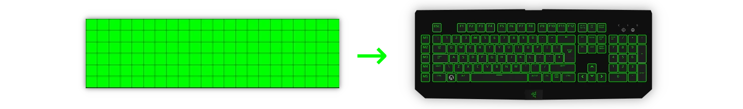
All devices that support individually addressable LEDs map to a grid by default. These can also be visually mapped to a crafted graphic as well.
Contents
- Preparing the repository
- Add to map index
- Creating the device SVG
- Creating the scan code JSON (keyboards/keypads only)
- Testing the changes
Preparing the repository
-
Fork the polychromatic repository
 on GitHub.
 -
Clone the repository to your computer.
git clone https://github.com/YOUR_GITHUB_USERNAME/polychromatic.git
Add to map index
The following file contains all the mappings the user can choose from:
data/devicemaps/maps.json
Append your device to the end of this list.
"Razer BlackWidow Chroma (British)": {
    "filename": "blackwidow_m_keys_en_GB.svg",
    "cols": 22,
    "rows": 6,
    "locale": "en_GB",
    "scancode": "blackwidow_m_keys.json"
},
| Key | Data Type | Description |
|---|---|---|
<root> |
str | The name of the device. As this isn’t translated, use the localized name if applicable. For example, “Razer Blade 2018 (Deutsch)” for a German keyboard layout. |
filename |
str | Base name of the SVG file to be created |
cols |
int | 1-based number of columns (X axis) |
rows |
int | 1-based number of rows (Y axis) |
locale |
str / null
|
Only applies to keyboards to indicate key layout. Leave null if not applicable. |
scancode |
str / null
|
Points to another JSON file that maps scan codes to the matrix. Leave null if not applicable. |
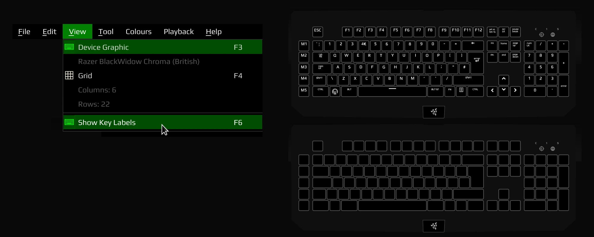
If you don’t know the
colsorrowsfor the device, click Device Info from the Controller’s Devices tab.
Creating the Device SVG
This is a vector graphic that looks similar to the actual hardware, but it contains additional metadata so Polychromatic knows where the LEDs are.
Creating the Device SVG: Shapes and paths
You’ll need an SVG editor, such as Inkscape
Inkscape adds additional metadata that serves no purpose for the application’s operation. When saving for the final time, please save as Plain SVG
First, you’ll want to perform the usual drawing/editing of the device.
If there is already an identical graphic in data/devicemaps/, feel free to copy
that one as a starting point.
Otherwise, it may help to embed a picture of the device and create paths for the base unit and its individual LEDs.
If you do embed an image to assist, don’t forget to remove it SVG when you’re done. Contributions with embedded raster images will not be accepted.
Polychromatic will be changing an object’s fill and stroke colour in the editor.
Make sure the shape/path has a sufficient stroke style (border). A stroke width
between 1.5px-2px is recommended.
Creating the Device SVG: IDs and class attributes
In Inkscape, open the XML Editor (Edit → XML Editor)
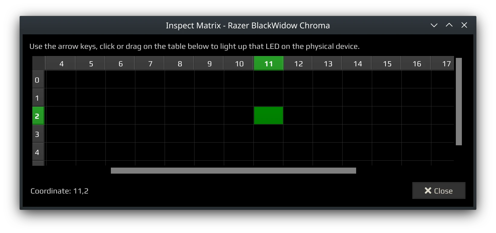
Have the co-ordinates of each LED ready. To find these out, open the Controller to the Devices tab, click Device Info and choose Inspect Matrix. Look at the physical hardware to confirm the LED’s position.
Assign each node of an LED:
| Attribute | Value |
|---|---|
class |
LED |
id |
The co-ordinate in this format: x0-y0 For example, x11-y2 for (11,2)
|
This is an example for the P key on the BlackWidow graphic:
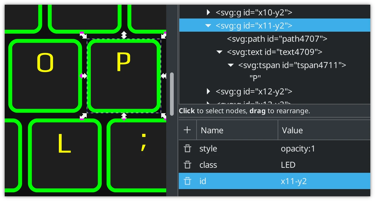
There can only be one ID! If there are multiple nodes that represent a specific LED, place those nodes into a group and assign the attributes to the parent
<g>tag.
When a key is illuminated in the editor, the fill and stroke of the node
(and any children) will be coloured too:
path, text, rect, circle
To exempt an object from having its colours changed, add an extra attribute:
| Attribute | Value | Response |
|---|---|---|
nostroke |
true |
Changes fill to black or white and clears stroke. Add this for key labels. |
nochange |
true |
Do nothing to fill or stroke
|
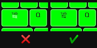
Here’s an example with the Tab key. There’s a symbol that should only be a fill colour, with no stroke:
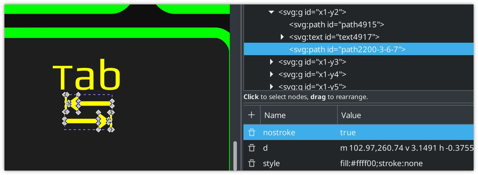
With and without the attribute:
Creating the Device SVG: Text Labels
If an LED has a label (like keyboard/keypad keys), set that object’s
class attribute to label.
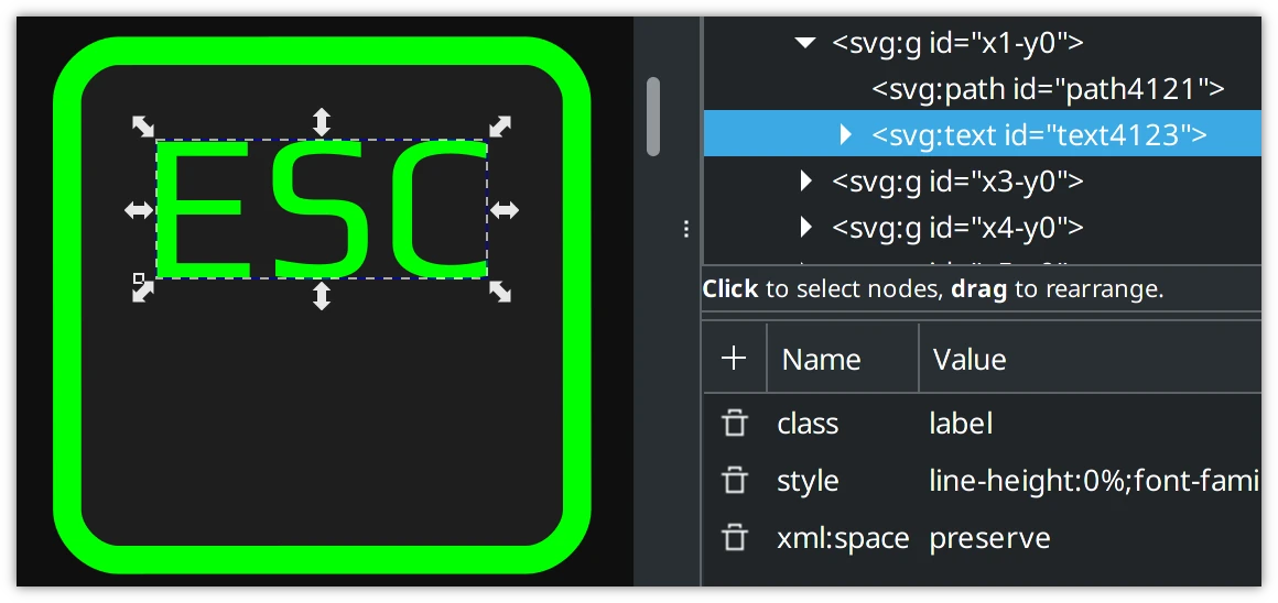
This allows the user to turn on/off key labels.
Key labels can be represented using the Play font for consistency.
If you use a different font to match your keyboard’s design, convert the text to path
to ensure it can be seen across different operating systems. Copyrighted non-free
fonts should be avoided.
Installing the Play font is not required, but it can help see things in Inkscape as they will in Polychromatic’s editor. Make sure any new text nodes have “Play” set for the font as opposed to the default sans serif.
Creating the scan code JSON
This only applies to keyboards and keypads.
A scan code is an integer describing the physical key. Polychromatic uses this to determine where the LED is physically located. This typically for a device with physical inputs that are recognised by the operating system as keystrokes.
Future stuff! This will be used in a future update to provide interactivity.
As an example, this graphic below shows how physical keys map out to the top-left region of a BlackWidow Chroma keyboard. 16 is the scan code for Q.
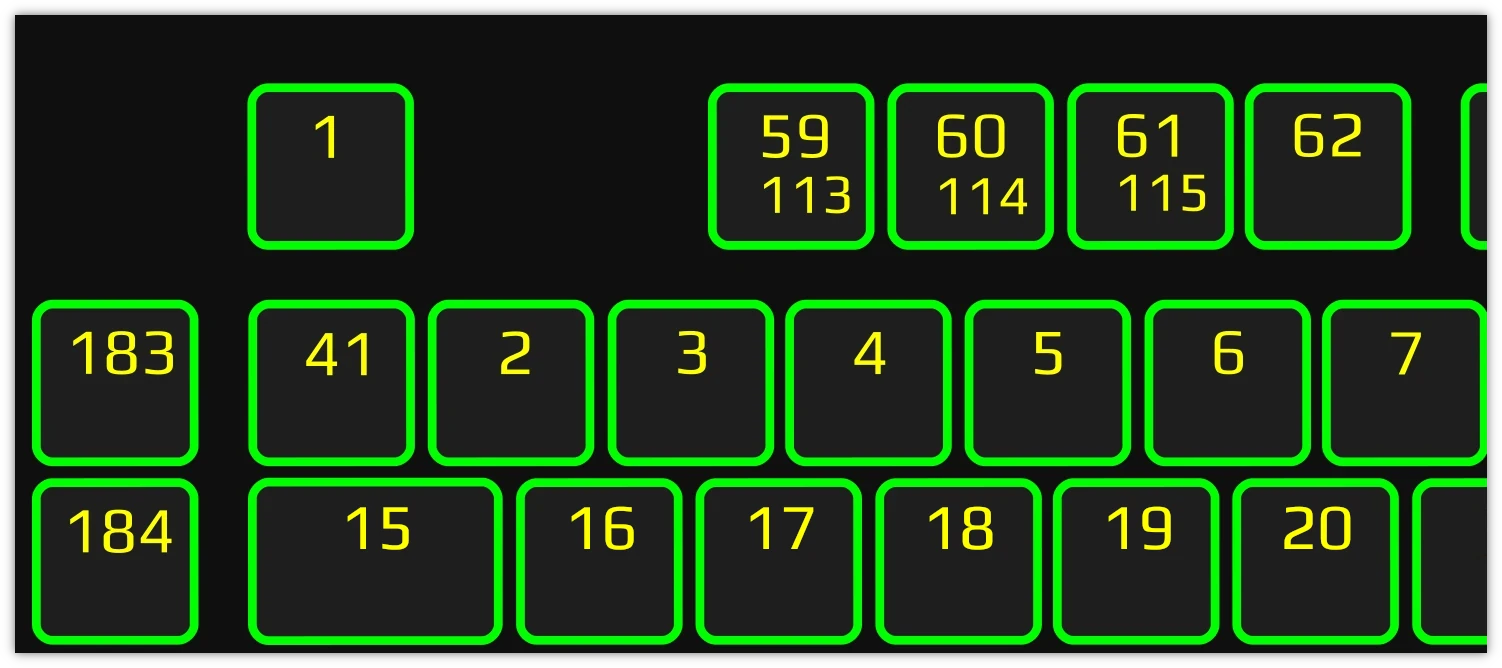
Not to be confused with key codes!
Key codes are similar, but instead describe the character/function of that key, like A or LEFT CTRL.
For instance, scan code
21translates to Y for English (QWERTY) keyboards, but would be Z on German (QWERTZ) keyboards. For the purposes of mapping LED positions, only scan codes are necessary.
In maps.json, you can specify an existing (or create a new) JSON file that
matches the scan code to the position on the LED matrix.
"1": [1, 0],

"59": [3, 0],
"113": [3, 0],
"60": [4, 0],
"114": [4, 0],
"61": [5, 0],
"115": [5, 0],
"62": [6, 0],
Scan codes can be determined by running evtest as root (the package may need
to be installed)
sudo evtest
After choosing the input file for the hardware, pressing Q outputs:
qEvent: time 1612876038.328661, type 4 (EV_MSC), code 4 (MSC_SCAN), value 70014
Event: time 1612876038.328661, type 1 (EV_KEY), code 16 (KEY_Q), value 0
In which the scan code 16 for this key.
type 1 (EV_KEY), code 16 (KEY_Q)
                 ^^^^^^^
This can be recorded into the JSON file and linked up to its position on the LED matrix.
Testing the changes
Once the files have been created/updated, it’s time to test the changes!
Run ./polychromatic-controller from the repository and try:
- Creating a new effect. Your new graphic should be listed here.
- Changing the colours of all LEDs (turn on “live preview” in Preferences)
- Double check the colours on-screen match the physical hardware.
If you created a scan code file, consider one final check. As these are for future use, there is no way to test within the application right now.
When everything’s in working order, commit your changes and hop on over to GitHub to create a pull request!